


Injection Molding
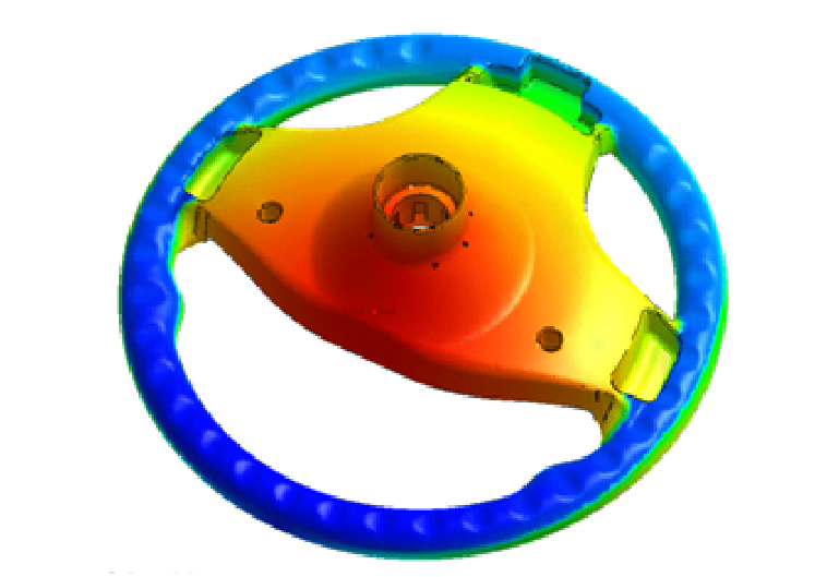
Multi-Component Molding (MCM)
Reactive Injection Molding

Variotherm

Conformal Cooling
Injection Compression Molding

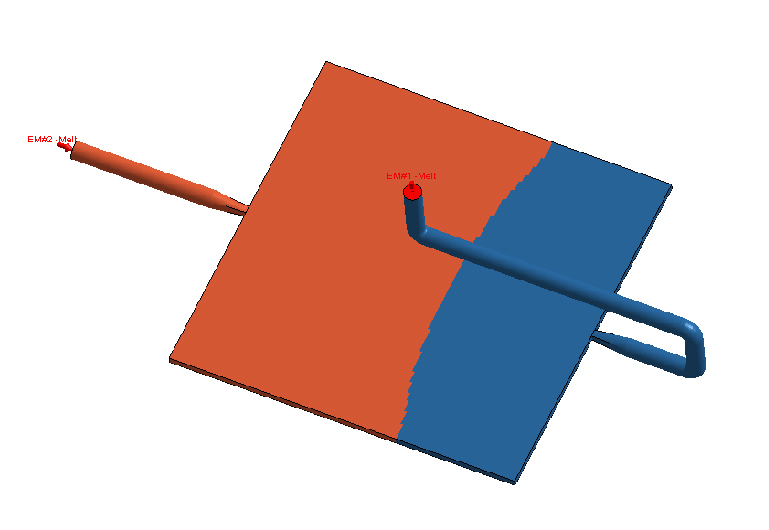
Bi-Injection Molding
")
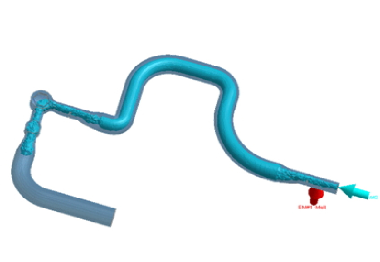
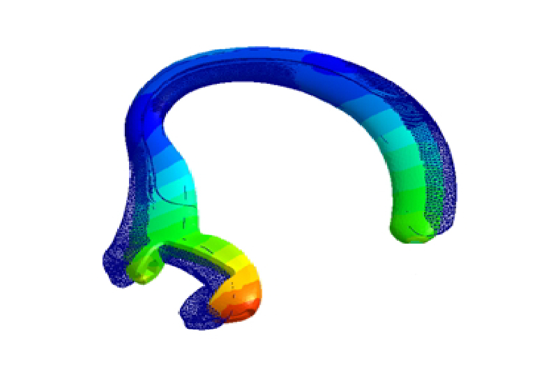
Gas-Assisted Injection Molding (GAIM)
")
Water-Assisted Injection Molding (WAIM)
Foam Injection Molding

Chemical Foaming Molding

Compression Molding

IC Packaging

Powder Injection Molding
RTM – Resin Transfer Molding

Investment Casting